Structural & mooring forces
Introduction
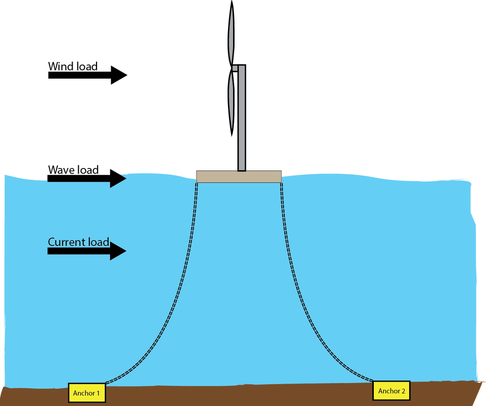
Floating wind turbines are under influence of different loads in their environment, namely:
On this page these forces are briefly described. Eventually a calculation tool is embedded where these forces are calculated for a floating wind turbine located in the North Sea near the coast of Norway. Finally the mooring forces for a catenary mooring system of the floating wind turbine is calculated.
- Wind loads
- Wave loads
- Current loads
On this page these forces are briefly described. Eventually a calculation tool is embedded where these forces are calculated for a floating wind turbine located in the North Sea near the coast of Norway. Finally the mooring forces for a catenary mooring system of the floating wind turbine is calculated.
Overview
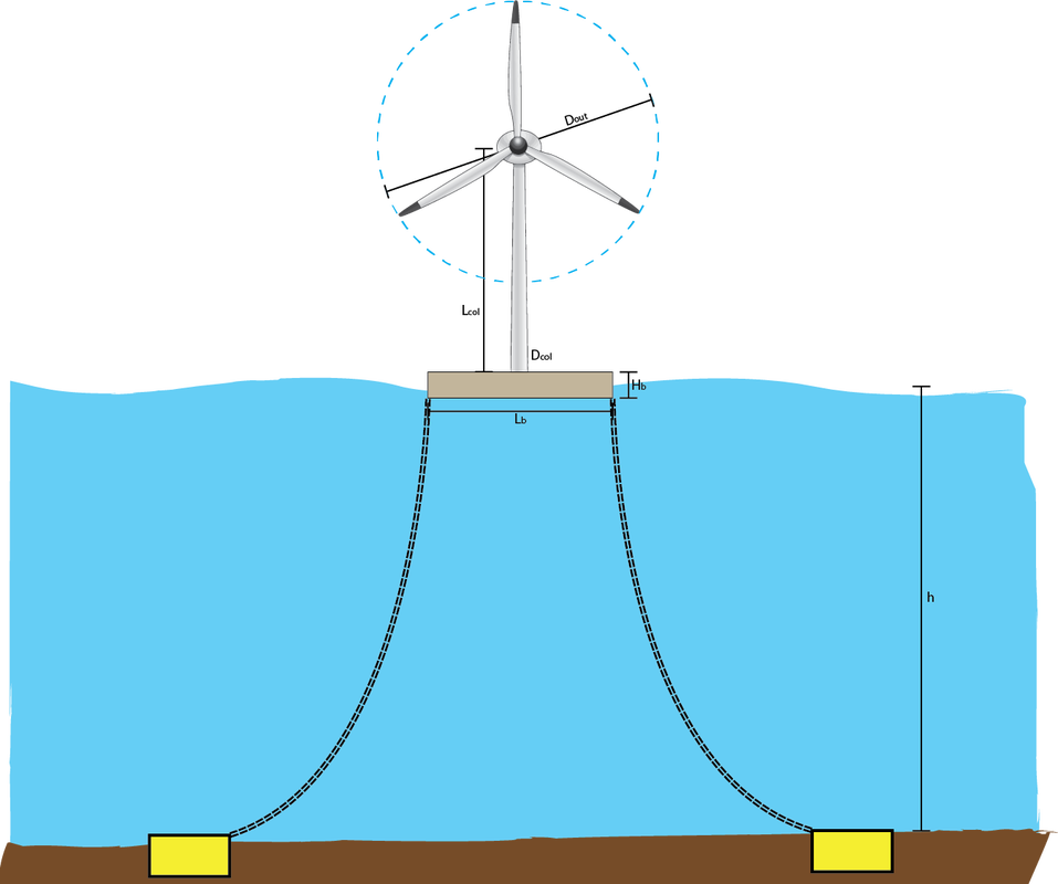
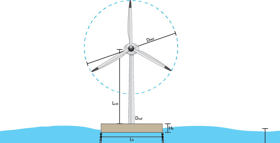
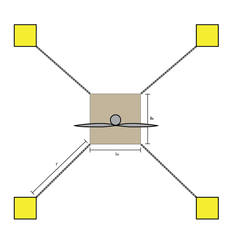
The structure contains three different sections on which these forces act namely the turbine, column and the barge. Please consult the illustrations below for more information on the used parameters.
Model simplification
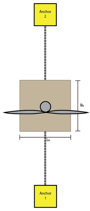
In this calculation tool the 3-dimensional mooring system has been reduced to a 2-dimensional situation. All three loads are from the same direction, in order to create a worst case scenario for design purposes. The conversion from 3D to 2D is depicted below in the figures.
It should be noted that the simplification from 4 mooring lines to a 2 line system may give a distorted view on the actual forces in the mooring line. However, this calculation tool can be perfectly used for preliminary design issues to estimate the global loads on a mooring system.
Model simplification
In this calculation tool the 3-dimensional mooring system has been reduced to a 2-dimensional situation. All three loads are from the same direction, in order to create a worst case scenario for design purposes. The conversion from 3D to 2D is depicted below in the figures.
It should be noted that the simplification from 4 mooring lines to a 2 line system may give a distorted view on the actual forces in the mooring line. However, this calculation tool can be perfectly used for preliminary design issues to estimate the global loads on a mooring system.
|
|
|
|
Explanatory theory
wind LOADS
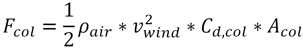
The wind loads are calculated on the column of the strucure and the turbine, which includes the turbine blades. The force on the column is calculated using the Bernoulli equation:
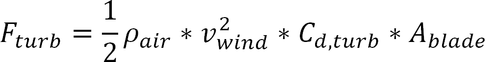
The force on the turbine is calculated using a simplification of the blade element momentum theory. The momentum theory assumes a stream tube. The turbine can be seen as an actuator disk, slowing the flow of air, creating a wake with reduced air flow velocity. The load that the actuator disk exerts on the flow to achieve this is the axial load. By defining an induction factor, the axial force of the actuator disk on the flow of air can be found using the momentum theory assuming incompressible, homogeneous and horizontal flow. The induction factor is defined combining both the undisturbed wind velocity and wind velocity at the actuator disk. This factor is simplified by using a drag coefficient. The Bernoulli equation gives:
The force on the turbine is calculated using a simplification of the blade element momentum theory. The momentum theory assumes a stream tube. The turbine can be seen as an actuator disk, slowing the flow of air, creating a wake with reduced air flow velocity. The load that the actuator disk exerts on the flow to achieve this is the axial load. By defining an induction factor, the axial force of the actuator disk on the flow of air can be found using the momentum theory assuming incompressible, homogeneous and horizontal flow. The induction factor is defined combining both the undisturbed wind velocity and wind velocity at the actuator disk. This factor is simplified by using a drag coefficient. The Bernoulli equation gives:
Wave loads
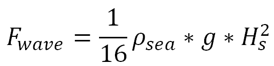
The wave particle kinematics can now be used to calculate the loads on a structure with the Morison Equation.
Current loads
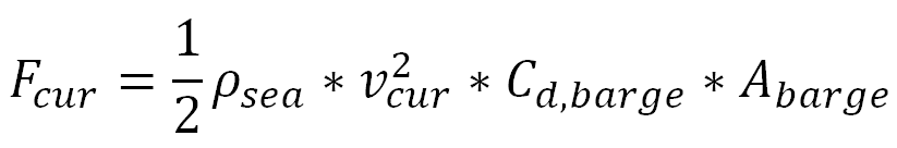
For a complete calculation on the hydrodynamic loads on the barge the current force is also calculated using the second term in the Morison Equation. As can be seen in the formula below a drag coefficient is incorporated in this term. Here the area of the barge on which the current force acts, is calculated by multiplying the length with the submerged part of the barge.
total loads
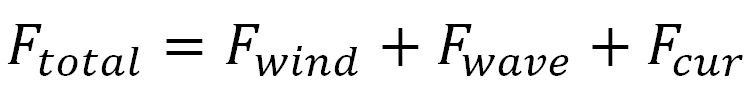
The total force is found by adding the different load components:
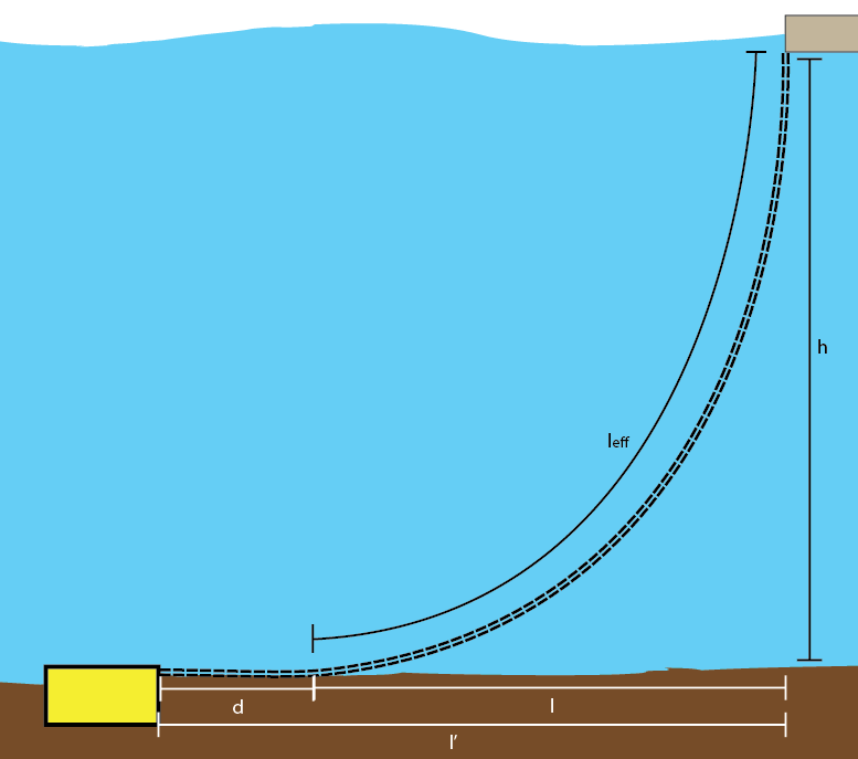
Offset
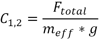
The calculate the offset first the catenary parameter is calculated by using the following formula:

The offset can now be calculated using:
Using the offset the catenary shape is calculated and can be seen in the output figures.
Using the offset the catenary shape is calculated and can be seen in the output figures.
